add_instrumental_effects_woden.py
Use this script to add instrumental effects to a WODEN uvfits output. The script is designed to be run on a single uvfits, so I suggest running add_woden_uvfits.py if you have 24 separate uvfits files. Read on for details on how different types of instrumental effects are added.
Adding noise
Warning
Everything is set for MWA highband simulations currently. This script needs developing.
The noise on cross-correlations is drawn for a normal distribution with a mean of zero and a standard deviation of \(\sigma_{\mathrm{cross}}\), which is calculated via the following (see Equation 6.50 in TMS 3rd edition for details):
where variables and there defaults are listed below
Variable |
Default |
Description |
|---|---|---|
\(T_{sky}\) |
\(228(\frac{\nu}{150\mathrm{MHz}})^{-2.53}\) |
The sky temperature in Kelvin; estimated by extrapolating values from 150 MHz |
\(T_{rec}\) |
50 |
The receiver temperature in Kelvin (estimate for MWA highband) |
\(A_{eff}\) |
20.35 |
The effective area of the antenna in square metres (estimate for MWA highband) |
\(\Delta\nu\) |
Value in |
The frequency resolution in Hz |
\(\Delta t\) |
Inferred from |
The time integration in seconds |
The noise is drawn randomly and added separately for the real and imaginary parts of each visibility, for all instrumental polarisations.
According to Kraus “Radio Astronomy” 2nd Edition, the noise on the auto-correlations is given by \(\sqrt{2}\sigma_{\mathrm{cross}}\). This noise is added in the same way as the crosses.
A comparison of measured noise from calibrated MWA data and noise added by add_instrumental_effects_woden.py for the cross-correlations is shown below:
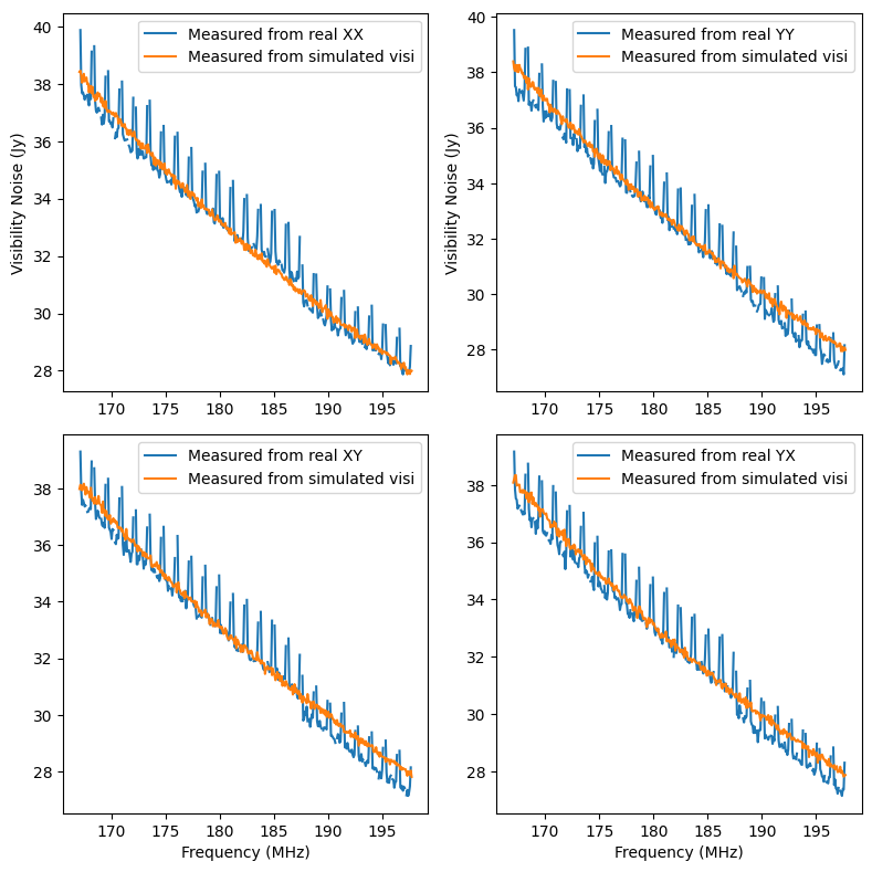
These noise values were estimated by differencing odd and even time step visibilities on 8s,80kHz averaged data. The real data are from 2014 when there was a digital gain jump, hence the discontinuity at around 187 MHz. The edges and centre of every MWA coarse band have also been flagged as they have extra noise from the bandpass. The simulated data includes the entire LoBES catalogue plus GLEAM for surrounding areas, with a total of around 200,000 sources.
Adding antenna (tile) gains and leakages
Each receiving element (often called a tile for MWA, called an antenna hereon) in a dual polarisation interferometer can have a gain (\(g_x, g_y\)) and leakage (\(D_x,D_y\)) term for each polarisation. Each visibility is a correlation of two antennas. WODEN implements any antenna gains and leakages by multiplying the visibility between tiles 1 and 2 through the following operation:
where \(V\) is a visibility in the uvfits file, \(\ast\) means the complex conjugate, and \(V^`\) is the visibility after the antenna gains and leakages have been applied. In WODEN 2.0.0, you can add a random frequency independent amplitude and a phase dependent slope to each antenna gain (see --ant_gain_amp_error and ``–ant_gain_phase_error``below for more detail). The leakage terms are calculated via Equation A4.5 from TMS third edition where
\( \begin{align} D_x = \Psi - i \chi \\ D_y = -\Psi + i \chi \end{align} \)
where \(\Psi, \chi\) are alignment errors of the dipoles. This equation is really designed for single antennas, but in the MWA case, you could imagine that all the dipoles in a tile are aligned aligned perfectly to the mesh, and the mesh is slightly offset, so the alignment errors for all dipoles are the same. The parameters. \(\Psi, \chi\) are set by the user via --ant_leak_errs so you can tune however much leakage you want.
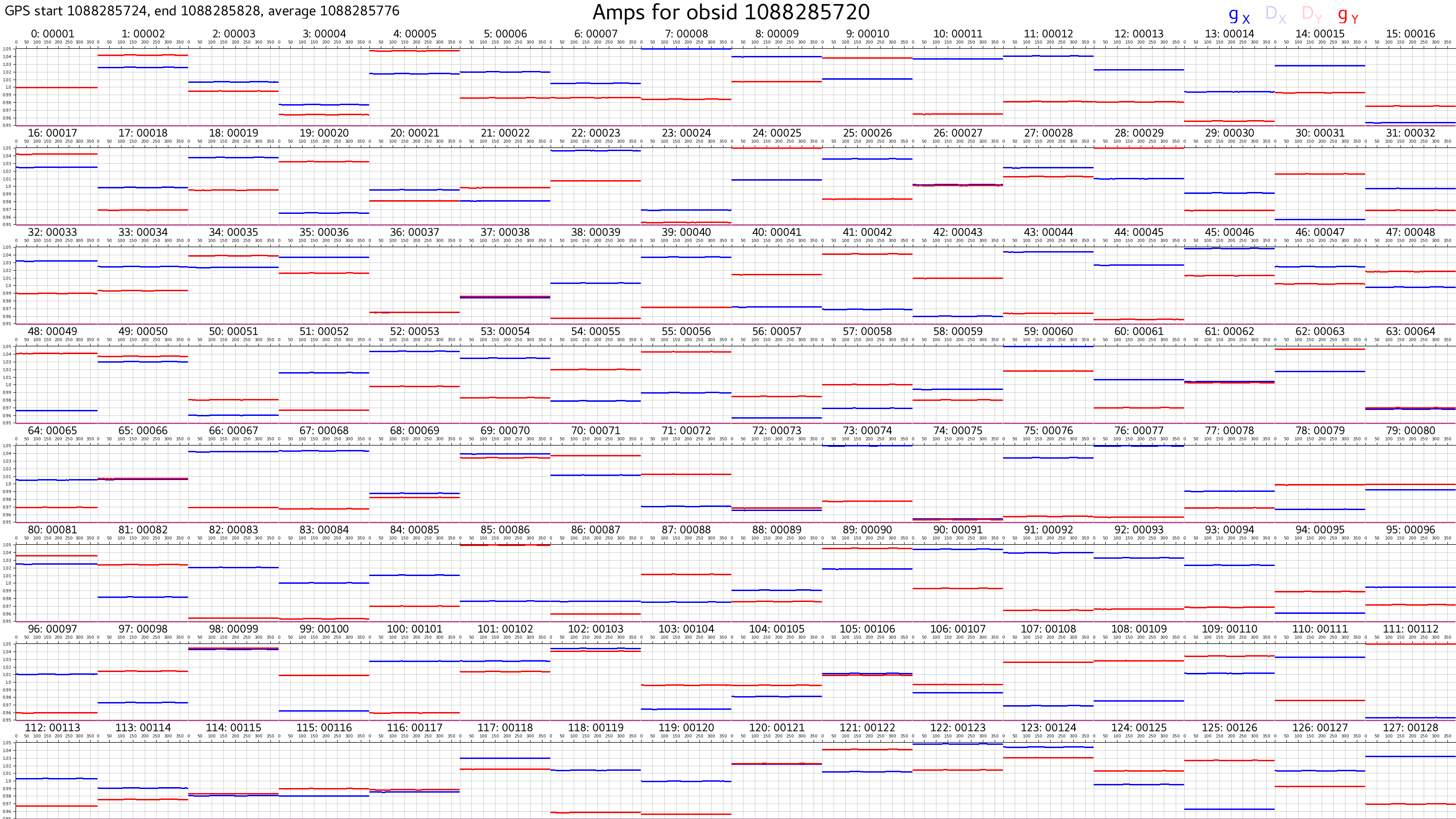
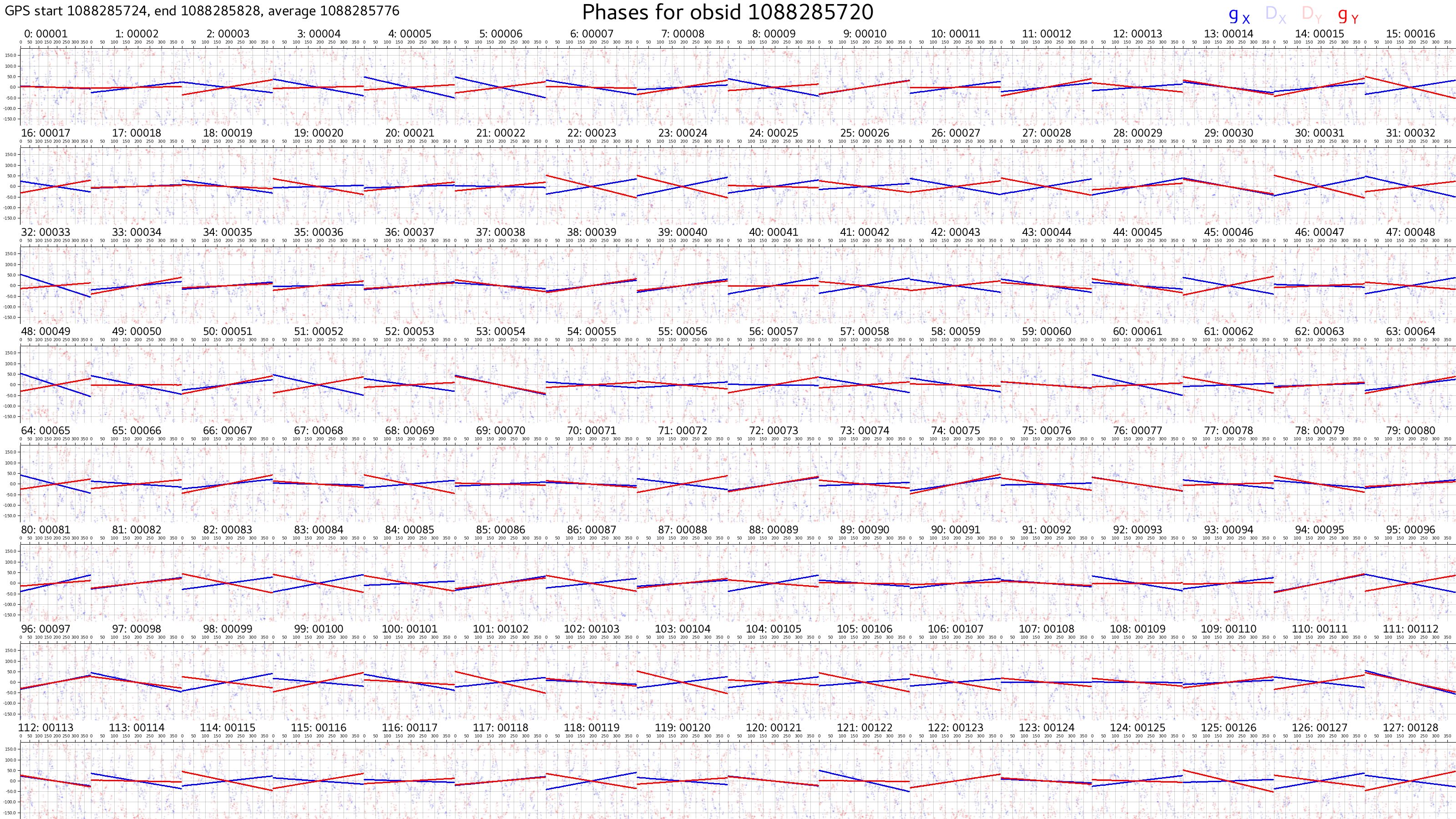
An example of calibration solutions obtained through hyperdrive when gains have been added by add_instrumental_effects_woden.py is shown below:
Cable reflections
Mismatched impedance at the cable ends can cause internal reflections that setup standing waves, adding frequency-dependent ripples to the visibilities. We follow the formalism from Beardsley et al (2016) to define the cable reflection gain seen by antenna \(i\) for polarisation \(\mathrm{pol}\) as
\( R_{\mathrm{pol},i}(\nu) = R_{0,i} \exp(-2\pi i \nu \tau_i), \)
where \(R_{0,i}\) is the complex reflection coefficient, and \(\tau_i\) is the time delay caused by the cable length connected to antenna \(i\). The time delay is given by
\( \tau_i = \frac{2l_i}{0.81c}, \)
where \(l_i\) is the length of the cable connected to antenna \(i\), and \(c\) is the speed of light. The factor 0.81 comes from the velocity factor of the cable, which we again take from Beardsley et al (2016). The cable lengths are listed in the MWA metafits file, so add_instrumental_effects_woden.py reads them directly from there. The reflection coefficient amplitudes are drawn from a uniform distribution between --cable_reflection_coeff_amp_min=0.02 and --cable_reflection_coeff_amp_max=0.01. These default values are based one a set of fitted FHD cable reflection solutions, but can be changed by the user. A random phase offset between 0 and 180 degrees is added to the reflection coefficient.
Warning
Really, the reflection coefficient tied to the cable length, but I’m just chucking a random one on each tile for now. Still answers question of whether we can fit them with hyperdrive, but FHD might average by cable type and then fit the reflections? Should the phase offset be the same for cable types?
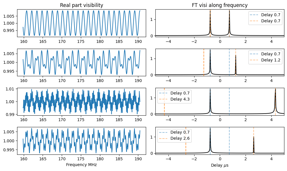
Applying these reflections to a simulation of a 1 Jy point source at zenith (so visibilities all of \(1 + 0i\)) allows us to test the applied reflections by Fourier transforming visibilities and checking the input delays:
Command line running arguments
Adds instrumental effects to a WODEN uvfits, given command line inputs
usage: add_instrumental_effects_woden.py [-h] [--uvfits UVFITS]
                                         [--output_name OUTPUT_NAME]
                                         [--noise_numpy_seed NOISE_NUMPY_SEED]
                                         [--inst_numpy_seed INST_NUMPY_SEED]
                                         [--add_visi_noise]
                                         [--visi_noise_int_time VISI_NOISE_INT_TIME]
                                         [--visi_noise_freq_reso VISI_NOISE_FREQ_RESO]
                                         [--cable_reflection_from_metafits CABLE_REFLECTION_FROM_METAFITS]
                                         [--cable_reflection_coeff_amp_min CABLE_REFLECTION_COEFF_AMP_MIN]
                                         [--cable_reflection_coeff_amp_max CABLE_REFLECTION_COEFF_AMP_MAX]
                                         [--ant_gain_amp_error ANT_GAIN_AMP_ERROR]
                                         [--ant_gain_phase_error ANT_GAIN_PHASE_ERROR]
                                         [--ant_leak_errs [ANT_LEAK_ERRS ...]]
                                         [--add_fine_channel_flags]
INPUT/OUTPUT OPTIONS
- --uvfits
Name of the uvfits file to add instrumental effects to e.g. filename.uvfits
Default:
False- --output_name
Name for output uvfits file, default: instrumental.uvfits
Default:
'instrumental.uvfits'- --noise_numpy_seed
A specific np.random.seed to use for adding noise, for reproducibility. Otherwise numpy is left to seed itself.
Default:
0- --inst_numpy_seed
A specific np.random.seed to use for instrumenal effects (other than noise), for reproducibility. Otherwise numpy is left to seed itself.
Default:
0
NOISE EFFECTS
- --add_visi_noise
Add visibility noise via the radiometer equation. Defaults to MWA-like parameters for reciever temperature and effective tile area
Default:
False- --visi_noise_int_time
Use a different integration time (seconds) to what is actually in the data to calculate the noise, e.g. even if you data is at 2s resolution, –visi_noise_int_time=60 will add the noise for a one minute integration.
Default:
False- --visi_noise_freq_reso
Use a different frequency channel width (Hz) to what is actually in the data to calculate the noise, e.g. even if you data is at 40kHz resolution, –visi_noise_freq_reso=1e+6 will add the noise for a channel width of 1MHz instead.
Default:
False
CABLE REFLECTION GROUP
- --cable_reflection_from_metafits
Given a metafits file with cable length information, add in cable reflections to the antenna gains. This will use the –cable_reflection_coeff_amp_min/cable_reflection_coeff_amp_max to set the magnitude.
Default:
False- --cable_reflection_coeff_amp_min
Amplitude of the cable will be drawn from a uniform distribution between –cable_reflection_coeff_amp_min and –cable_reflection_coeff_amp_max. Default is 0.002. (based on FHD fits)
Default:
0.002- --cable_reflection_coeff_amp_max
Amplitude of the cable will be drawn from a uniform distribution between –cable_reflection_coeff_amp_min and –cable_reflection_coeff_amp_max. Default is 0.01. (based on FHD fits)
Default:
0.01
ANTENNA (tile) GAIN EFFECTS
- --ant_gain_amp_error
Add a single multiplicative gain error per antenna, of 1 +/- the value given (e.g. gains between 0.95 and 1.05 if –ant_gain_amp_error=0.05.
Default:
0- --ant_gain_phase_error
Add a phase error (degrees) per antenna, which will make a frequency dependent phase gradient between value to value, e.g if –ant_gain_phase_error=10, a phase error of up to -10 deg will be added to the lowest frequency, a phase error of up to +10 deg will be added to the highest frequency, with a smooth graident over phases added for all other frequencies.
Default:
0- --ant_leak_errs
Use as –ant_leak_errs psi_err chi_err (degrees). Adds an engineering tolerance error for linear dipole alignment (see TMS eqn A4.5) to add leakage terms to the antenna Jones matrix. This leakage is based off two angles where Dx = psi_err - 1j*chi_err and Dy = -psi_err + 1j*chi_err. A random angle between 0 and the given value will be added for each angle.
Default:
[0, 0]
FLAGGING
- --add_fine_channel_flags
Add the standard fine channel flags due to bandpass shape, e.g. if data is 40kHz resolution, flag channels 0 1 16 30 31 in each coarse band.
Default:
False
Function documentation
- add_instrumental_effects_woden.add_complex_ant_gains(args: Namespace, uvfits: UVFITS)[source]
Add complex antenna gains to the UVFITS object.
- Parameters:
args (Namespace) – Namespace object containing command line arguments.
uvfits (UVFITS) – UVFITS object containing visibilities to which antenna gains will be added.
- Returns:
UVFITS object with antenna gains added.
- Return type:
UVFITS
- add_instrumental_effects_woden.add_visi_noise(args: Namespace, uvfits: UVFITS)[source]
Adds instrumental thermal noise to the visibilities of a UVFITS object, given the input args. The noise is calculated using the radiometer equation. Everything is currently hardcoded to MWA values.
- Parameters:
args (argparse.Namespace) – Command-line arguments parsed by argparse.
uvfits (UVFITS) – UVFITS object to which noise will be added.
- Returns:
The input UVFITS object with noise added to its visibilities.
- Return type:
UVFITS
- add_instrumental_effects_woden.apply_antenna_jones_matrices(visibilities, antenna_jones_matrices, b1s, b2s)[source]
Apply the antenna Jones matrices to the visibilities for a set of antenna pairs defined by b1s, b2s
- Parameters:
visibilities (numpy.ndarray) – The visibilities to which the Jones matrices will be applied. The shape of the array should be (Nvis, Nfreqs, 4), where Nvis is the number of visibilities, Nfreqs is the number of frequency channels, and the last dimension contains the complex visibilities for all 4 instrumental stokes polarisations.
antenna_jones_matrices (numpy.ndarray) – The Jones matrices for each antenna in the array. The shape of the array should be (Nants, Nfreqs, 2, 2), where Nants is the number of antennas and the last two dimensions contain the complex Jones matrix for each antenna.
b1s (numpy.ndarray) – The indices of the first antenna in each baseline.
b2s (numpy.ndarray) – The indices of the second antenna in each baseline.
- Returns:
The visibilities with the Jones matrices applied. The shape of the array is the same as the input visibilities.
- Return type:
numpy.ndarray
- add_instrumental_effects_woden.create_cable_reflections(args: Namespace, uvfits: UVFITS) Tuple[ndarray, ndarray][source]
Given the input arguments and a UVFITS object, create the cable reflections for the x and y pols.
- Parameters:
args (Namespace) – Namespace object containing command line arguments.
uvfits (UVFITS) – UVFITS object containing visibilities to which reflections will be added.
- Returns:
reflections_x, reflections_y – 2D arrays of reflections to add to the x and y pols, of shape (num_antennas, num_freqs).
- Return type:
np.ndarray, np.ndarray
- add_instrumental_effects_woden.create_single_pol_reflections(freqs: ndarray, cable_reflection_coeff_amp_min: float, cable_reflection_coeff_amp_max: float, delays: ndarray) ndarray[source]
Calculate the reflections caused by a set of cables with a given delays, assigns a random reflection coefficient amplitude for the given frequency vector. Returns a 2D array of shape (len(delays), len(freqs)).
- Parameters:
freqs (np.ndarray) – Frequencies to calculate the reflections at (Hz)
cable_reflection_coeff_amp_min (float) – Minimum amplitude of the cable reflection coefficient.
cable_reflection_coeff_amp_max (float) – Maximum amplitude of the cable reflection coefficient.
delays (np.ndarray) – Delays of the cable reflections (seconds)
- Returns:
reflections – A 2D array of reflections of shape (len(delays), len(freqs)) for all delays and frequencies.
- Return type:
np.ndarray
- add_instrumental_effects_woden.get_cable_delay(length, velocity_factor=0.81)[source]
Calculate the delay imparted by a cable of specific length and velocity factor.
- Parameters:
length (float) – Length of the cable in meters.
velocity_factor (float) – Velocity factor of the cable (0.81 from Beardsley et al. 2016)
- Returns:
The delay of the cable in seconds.
- Return type:
float
- add_instrumental_effects_woden.get_parser()[source]
Runs the argument parser to get command line inputs - used by sphinx and argparse extension to unpack the help below into the online readthedocs documentation.
- Returns:
parser – The populated argument parser used by add_instrumental_effects_woden.py
- Return type:
argparse.ArgumentParser
- add_instrumental_effects_woden.main(argv=None)[source]
Adds instrumental effects to a WODEN uvfits, given command line inputs
- Parameters:
argv (_type_, optional) – Will be parsed from the command line if run in main script. Can be passed in explicitly for easy testing
- add_instrumental_effects_woden.make_antenna_jones_matrices(num_antennas: int, num_freqs: int, gain_amp_err=0.0, gain_phase_err=0.0, leak_psi_err=0.0, leak_chi_err=0.0)[source]
Given input error parameters, create a set of instrumental Jones matrices for each antenna and frequency.
- Parameters:
num_antennas (int) – Number of antennas.
num_freqs (int) – Number of frequencies.
gain_amp_err (float, optional) – Maximum amplitude error (as a fraction of the true gain) to apply to each antenna, by default 0.0
gain_phase_err (float, optional) – Maximum phase error (in degrees) to apply to each antenna.
leak_psi_err (float, optional) – Small engineering error on the linear polarization alignment of the dipoles, represented by psi_err, by default 0.0
leak_chi_err (float, optional) – Small engineering error on the linear polarization alignment of the dipoles, represented by chi_err., by default 0.0
- Returns:
antenna_jones_matrices – Complex antenna jones matrices for all antennas, of shape (num_antennas, num_freqs, 2, 2)
- Return type:
np.ndarray
- add_instrumental_effects_woden.make_jones_leakage(num_antennas, num_freqs, leak_psi_err=0.0, leak_chi_err=0.0)[source]
Generate Jones leakage terms for a set of antennas and frequencies.
- Parameters:
num_antennas (int) – Number of antennas.
num_freqs (int) – Number of frequencies.
leak_psi_err (float, optional) – Small engineering error on the linear polarization alignment of the dipoles, represented by psi_err.
leak_chi_err (float, optional) – Small engineering error on the linear polarization alignment of the dipoles, represented by chi_err.
- Returns:
Dx (numpy.ndarray) – Jones leakage term for the x-polarization.
Dy (numpy.ndarray) – Jones leakage term for the y-polarization.
- add_instrumental_effects_woden.make_single_polarsiation_jones_gain(num_antennas, num_freqs, amp_err=0.05, phase_err=10)[source]
Generate a Jones gain matrix for a single polarisation, with random amplitude and phase errors.
- Parameters:
num_antennas (int) – Number of antennas in the array.
num_freqs (int) – Number of frequency channels.
amp_err (float, optional) – Maximum amplitude error (as a fraction of the true gain) to apply to each antenna. Default is 0.05.
phase_err (float, optional) – Maximum phase error (in degrees) to apply to each antenna. Default is 10.
- Returns:
jones_entry – Complex Jones gain matrix of shape (num_antennas, num_freqs), with the first row set to (1+0j).
- Return type:
ndarray
- add_instrumental_effects_woden.visibility_noise_stddev(freq_vec, time_res, freq_res, Trec=50, Aeff=20.35)[source]
For an input set of frequencies, and time in seconds, calculate the visibility noise using the radiometer equation. default MWA values are given.
See Equation 6.50 in TMS Third Edition for details of radiometer eq.
- Parameters:
freq_vec (numpy array, float) – Vector of fine channels in Hz.
time_res (float) – Observation time in seconds
freq_res (float) – Fine channel width in Hz, default is 80kHz.
Trec (float) – Reciever temperature in Kelvin.
Aeff (float) – Effective MWA tile area, default is 20.35 for chan 136. Chan 136 is the default middle channel for high band obs.
- Returns:
sigma – \(\sigma\) values for each given frequency
- Return type:
numpy array, float